Fluid Mechanics and Energy Laboratory
In the Fluid Mechanics and Energy laboratory, Pelton and Francis Turbines, Orifice Measurement, Manometer Calibration, Pressure Center Determination, Pressure Measurement, Experimental Vortex, Reynolds Number Measurement, Pneumatic Control and Friction Losses in Flow Through Pipe Measurement applications are carried out experimentally for undergraduate students. In addition to these, they utilize wind tunnel and food drying system in project applications. Pumps and fans and their parts are explained to the students visually. In addition, an airplane engine and its equipment are introduced to the students.
The devices belonging to the fluid mechanics and energy laboratory are given in Table 1.
Table 1: Equipment of the Fluid Mechanics and Energy Laboratory
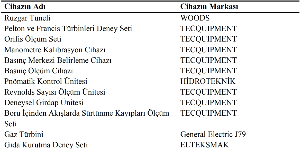
Students are shown the principles of turbine operation and different turbine types experimentally on the Pelton and Francis Turbines experimental set (Figure 1). Here, turbine performances can be compared at different blade spans and variable net head.
In the laboratory, Orifice Measurement (Figure 2), Manometer Calibration (Figure 3), Pressure Center Determination (Figure 4), Pressure Measurement (Figure 5), Experimental Vortex (Figure 6), Reynolds Number Measurement (Figure 7) and Friction Losses in Flow Through Pipe Measurement (Figure 8) applications are performed experimentally for undergraduate students. As an example of pneumatic applications, students examine a simple pneumatic circuit (Figure 9) in practice.
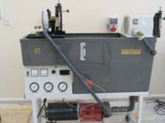
Figure 1: Pelton and Francis Turbines Experimental Set
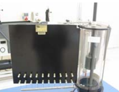
Figure 2: Orifice Measurement Set
Figure 3: Manometer Calibration Device
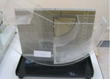
Figure 4: Center of Pressure Determination Device
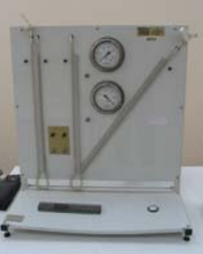
Figure 5: Pressure Measurement Device
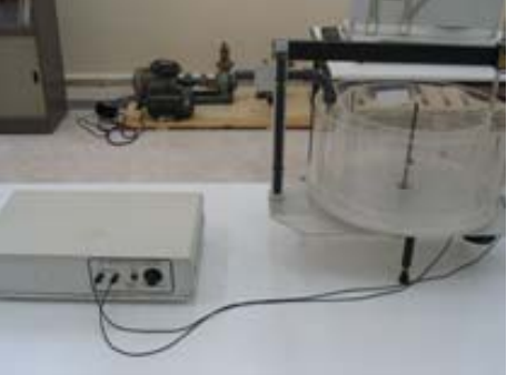
Figure 6: Experimental Vortex Unit
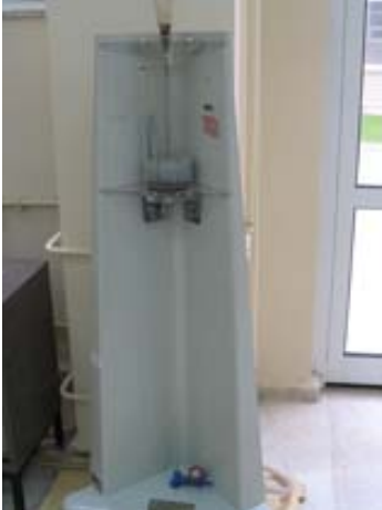
Figure 7: Reynolds Number Measurement Unit
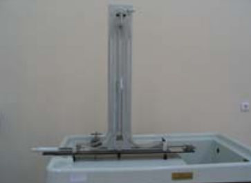
Figure 8: Friction Losses Measurement Set for Through-Pipe Flows
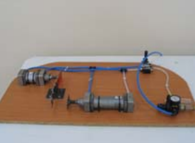
Figure 9: Pneumatic Control Unit
In addition, an airplane engine and its equipment (Figure 10) are introduced to the students. In addition, they benefit from the wind tunnel (Figure 11) and food drying system (Figure 12) in their project applications.
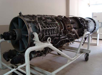
Figure 10: J79 Gas Turbine
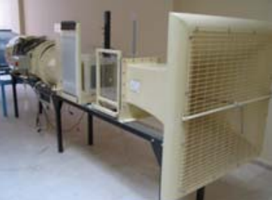
Figure 11: Wind Tunnel
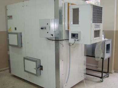
Figure 12: Food Drying Experimental Set