Clean Energy House
A building was constructed on the Kınıklı Campus of Pamukkale University where energy research is conducted and used as a laboratory. This building with a floor area of 165 m2, which was financed by Bereket Enerji and donated to the university, is called the “Clean Energy House”. The 5 kW solar-hydrogen system and the system for meeting the heating and hot water needs of the house by utilizing solar energy are supported by the State Planning Organization (SPO) with the project code DPT2003K120950. These systems, which were established with the project titled “Obtaining Hydrogen from Solar Energy Using Solar Cells and Meeting the Electricity and Heat Needs of a House with Solar Energy”, were implemented in the “Clean Energy House”.
The devices belonging to the clean energy house are given in Table 1.
Table 1: Devices of the Clean Energy House
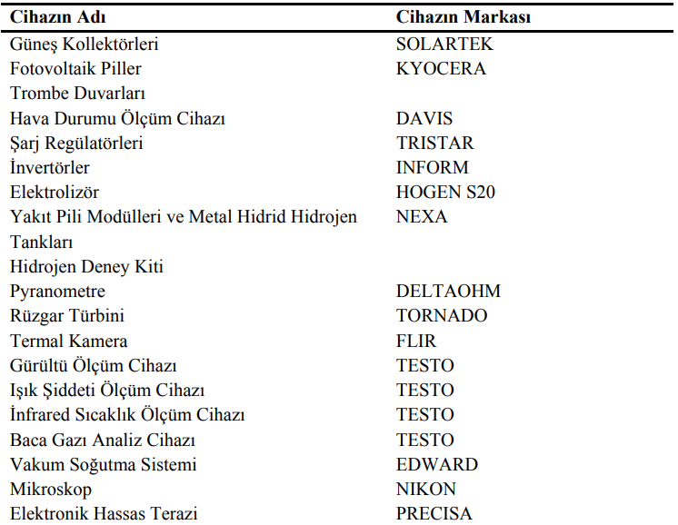
The heat demand of the house is met by using aluminum and copper selective surface solar collectors with a total surface area of 40 m2 (Figure 1). In addition to active heating with solar energy, passive heating support is realized with Trombe walls on the south façade of the house (Figure 2).
The electricity generation system consists of two main components. These are solar cell panels (Figure 3) and fuel cells (Figure 4). Thus, electricity generation can be met from the sun and hydrogen. For this purpose, solar cell panels are used where electricity can be generated directly from solar energy. In addition, hydrogen, which is the energy carrier, is obtained by using the electricity generated from solar energy in the electrolysis process (Figure 5) and stored in solid form (in metal hydride tanks) and electricity can be generated from hydrogen in fuel cells when needed. Charge regulators and inverters are used to store solar energy in batteries and then use it for household needs (Figure 6).
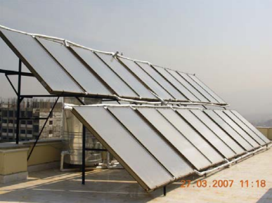
Figure 1: Solar Collectors
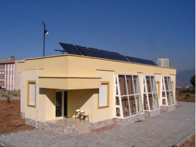
Figure 2: Trombe Walls
Figure 3: Photovoltaic Batteries
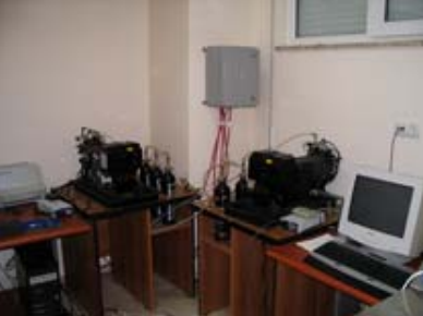
Figure 4: Fuel Cell Modules and Metal Hydride Hydrogen Tanks
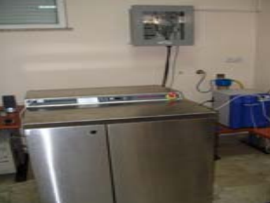
Figure 5: Electrolyzer

Figure 6: Charge Regulators and Inverters
Students can familiarize themselves with hydrogen systems and also perform experimental applications of the systems in this house (Figure 7). Various measurement techniques can also be demonstrated to students in the Clean Energy House. With different measurement techniques, solar radiation value measurement with pyranometer (Figure 8), temperature measurement with thermal camera (Figure 9) and infrared thermometer (Figure 10), noise measurement (Figure 11), light intensity measurement (Figure 12) can be performed. In addition, the working principle of the Flue Gas Analyzer (Figure 13), which is available in the laboratory for industrial applications, and the measurements made are explained to the students.
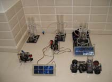
Figure 7: Hydrogen Experiment Kit

Figure 8: Pyranometer
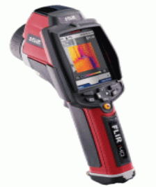
Figure 9: Thermal Camera

Figure 10: Infrared Temperature Measurement Device

Figure 11: Noise Measurement Device
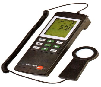
Figure 12: Light Intensity Meter

Figure 13: Flue Gas Analyzer
In the Clean Energy House, students are also introduced to the vacuum cooling system (Figure 14) and project students are given the opportunity to practice. Students can also use microscope (Figure 15) and precision balance (Figure 16) devices in their projects.

Figure 14: Vacuum Cooling System
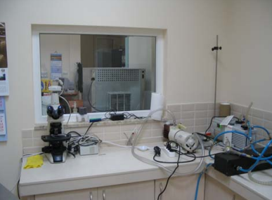
Figure 15: Microscope
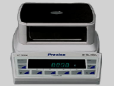
Figure 16: Electronic Precision Balance
In the Clean Energy House, a prototype wind turbine (Figure 17) is installed and students are given information about the use of wind energy. The weather measuring device (Figure 18) placed on the roof measures and records meteorological data instantaneously. With this device, students use values such as temperature, humidity, wind speed and solar radiation in their projects.

Figure 17: Wind Turbine
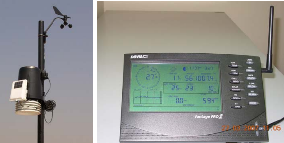
Figure 18: Weather Meter
Other Equipment in Composite Material Production Laboratory
Plastic injection processes are carried out with the plastic injection molding machine shown in Figure 19. Production with plastic injection molding machine is carried out by injecting the plastic material melted with the help of temperature into the injection mold with the help of pressure, shaping it and cooling it and removing it from the mold. The plastic injection molding machine has three main units: clamping (clamp), injection and mold. The machine dimensions are 1000 x 3000 x 1600 mm and has a material capacity of 150 g.
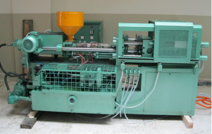
Figure 19: Plastic Injection Molding Machine
The crushing and shredding (granulating) processes of the material used in the plastic injection molding machine are carried out with the crushing machine shown in Figure 20. The dimensions of the machine are 1000 x 1500 x 2000 mm. The plastic crushing machine crushes all kinds of plastics (PP, PE, LDPE, HDPE, ABS, PS, PET, PVC) into granules to be used in the plastic injection molding machine.
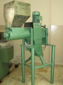
Figure 20: Plastic Crushing Machine
The desktop laboratory scale polyurethane injection molding machine is shown in Figure 21. It has polyol and isocyanate tanks and can mix the two liquids in the desired ratio in a mixer.
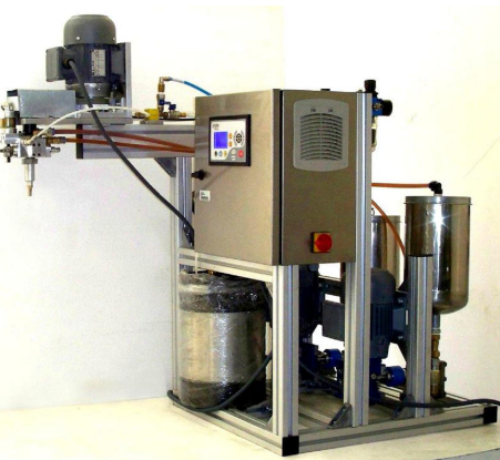
Figure 21: Polyurethane Injection Molding Machine
Figure 22 shows the homogenizer and mechanical mixer that can be used in different production processes.
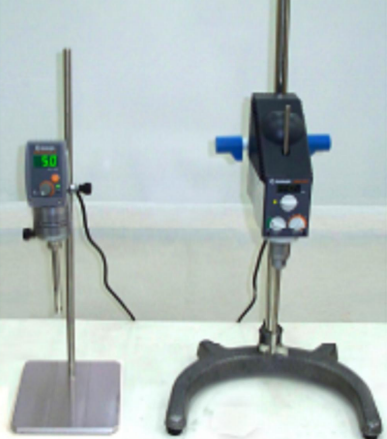
Figure 22: Homogenizer and Mechanical Mixer